CAD-to-Fabrication: Working from Customer Drawings in Caldwell
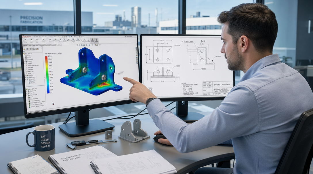
Redband Fabrication is a steel processing and fabrication company, not an engineering firm. We fabricate to customer-provided engineered drawings and specifications, and our CAD and CAM software, SolidWorks and ProNest, turns your drawings and digital part files into cut, formed, and welded steel components.
How We Work with Customer Files
The gap between a digital model and a physical part is where fabrication shops introduce error. We close that gap with a direct CAD-to-fabrication workflow:
- Drawing intake: We review your drawings and part files, including DXF, DWG, and STEP formats, along with material specifications and quantities.
- Modeling: Where needed, parts are modeled in SolidWorks to verify geometry and fit for fabrication.
- Nesting: Parts are nested in ProNest to optimize material yield on the plasma table.
- Cutting and forming: Components are cut on our Hypertherm HPR130XD AutoGas plasma system and formed on our 150-ton press brake with a 10-foot bed.
- Welding: Welded assemblies are completed with GMAW and FCAW welding. Structural steel welding with AWS D1.1 qualifications available based on project requirements.
What We Can Handle
Our fabrication capability covers parts that standard processing shops handle every day:
- Structural steel components: splice plates, base plates, gusset plates, brackets, and angles
- Custom industrial parts: brackets, supports, and assemblies fabricated to customer drawings
- Wear components: AR400 and AR500 parts for industrial and agricultural equipment
- Production runs: repeat orders with consistent parts from the same programming and nesting
What We Do Not Provide
Redband does not provide professional engineering services, engineer-stamped drawings, or structural engineering consultation. We fabricate to the engineered drawings and specifications your design team provides. If your project needs engineering input, that stays with your engineer or architect.
Whether you are a procurement officer sourcing steel components for Canyon County manufacturing, a structural steel contractor, or an industrial operation needing custom parts, send us your drawings and we will quote your project.
Serving the Treasure Valley
Redband Fabrication is located in Caldwell, Idaho, serving industrial customers across the Treasure Valley, including Nampa, Meridian, Boise, and Canyon County.
Frequently Asked Questions
Do I need CAD files to get a quote from Redband Fabrication?
No. We work from customer-supplied drawings and digital part files. If you have drawings, DXF, DWG, or STEP files, send them along with material specifications and quantities. If you only have sketches or existing parts, contact us to discuss your project.
What CAD file formats do you accept?
We work from customer-supplied drawings and digital part files, including DXF, DWG, and STEP formats. We use SolidWorks for modeling and ProNest for nesting and CAM.
Can you reverse-engineer a part from a sample?
We can work from customer drawings, samples, or specifications for custom replacement parts. Contact us with your part or sample to discuss the scope.